By George House/08,May,2026
The parts of a door lock vary with the lock family, but most assemblies combine an operating trim, a latch or bolt, an internal mechanism, a strike and fixings. Understanding these components helps with product selection, door preparation, installation and maintenance.
A lock must also fit the rest of the door and opening package. Door thickness, material, handing, frame construction, clearances and project requirements affect which hardware can be used.
First identify the lock family
A cylindrical or bored lock, mortise lock, tubular latch, deadbolt, multipoint system, rim device and sliding-door lock do not share exactly the same parts. The component names below are common reference points, but the manufacturer’s product data and template control the final preparation.
- Cylindrical or bored lock: a chassis fits through cross-bored holes in the door.
- Mortise lock: a lock case is recessed into a pocket in the door edge.
- Deadbolt: a bolt is operated separately or as part of an interconnected assembly.
- Multipoint lock: one operating action engages several locking points along the edge.
- Sliding or pocket-door lock: compact hardware is shaped for a sliding leaf and limited edge depth.
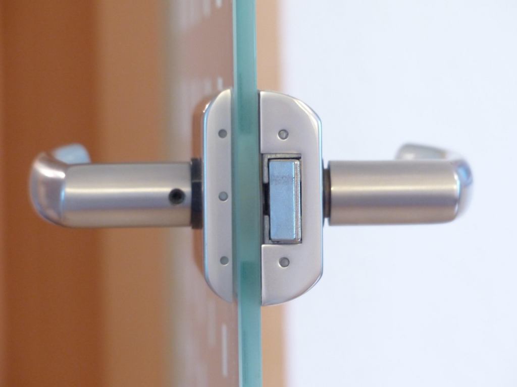
(Source)
Main visible parts
Lever, knob or pull
The operating trim is the part a user touches. A lever or knob may retract a latch, while a pull may be paired with a separate deadbolt or roller catch. Confirm projection, grip, return shape, finish and clearance from the frame, glass or adjacent hardware.
Rose, escutcheon and trim plate
The rose or escutcheon covers the door preparation and supports the visible hardware. It may be round, square or elongated. The selected trim must cover the bore or mortise preparation without conflicting with panels, glazing beads or decorative profiles.
Cylinder and keyway
The cylinder is the keyed component on many mechanical locks. A pin-tumbler cylinder uses a plug and pins, but other cylinder formats and electronic credentials work differently. Specify the cylinder type, length, keying requirement, finish and compatibility with the lock case or chassis.
Concealed working parts
Latch bolt and deadbolt
A spring latch retracts when the handle operates and returns when released. A deadbolt is positively thrown and retracted by a key, thumbturn or connected mechanism. The two functions should not be confused: their operation, projection and intended use differ.
Spindle, follower, cam and tailpiece
These parts transfer movement from the lever, knob, key or thumbturn to the internal mechanism. The exact arrangement depends on the lock type. Correct length and engagement are important; incompatible trim and lock bodies may assemble poorly even when the finish matches.
Lock case or chassis
The case or chassis holds the mechanism and fixes it within or through the door. A mortise case requires a defined pocket, faceplate and fixing pattern. A cylindrical chassis uses a different bore preparation. Never cut the door from a generic diagram when a product template is available.
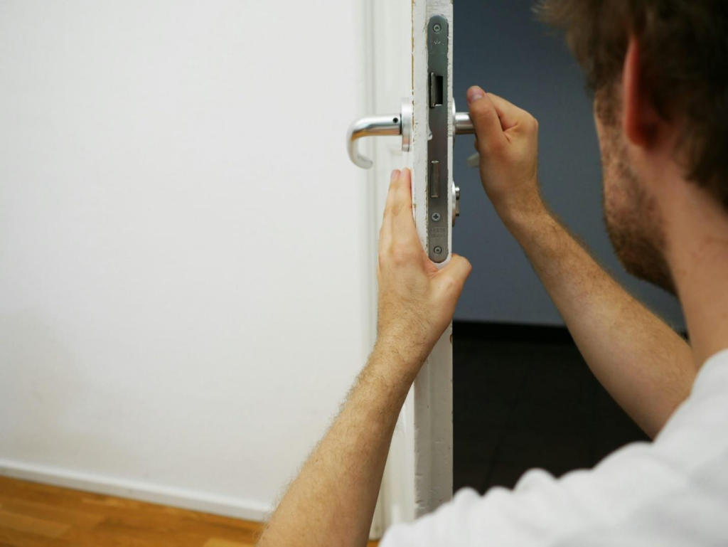
(Source)
Strike, frame and door preparation
The strike receives the latch or bolt at the frame. Its shape, lip, box, fixings and alignment must suit the lock and frame construction. Security performance depends on the complete tested or specified assembly, including the door, frame, strike and anchors—not on the strike plate alone.
Review the broader parts of a door before detailing the lock. Record door thickness, stile width, backset, center height, edge preparation, bore sizes, frame material, stop position and gap. Finished floor level and seals can also affect alignment.
Installation quality matters. The alignment checks used when installing an exterior door—plumb frame, controlled gaps and stable fixings—help the latch enter the strike without binding.
How a common keyed lock operates
In a typical pin-tumbler cylinder, the correct key positions pin pairs so the plug can rotate. Rotation moves a cam or tailpiece, which operates the latch or bolt mechanism. When the key is removed, the pins return to a blocking position. This explanation does not apply to every mechanical, multipoint or electronic lock.
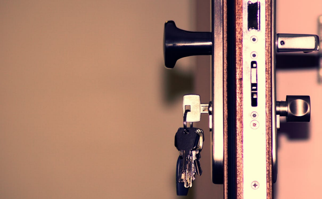
(Source)
Selection and scheduling checklist
| Field | Record in the hardware schedule |
|---|---|
| Opening | Door/frame type, thickness, material, handing and use |
| Lock | Family, function, backset, case size and latch/bolt detail |
| Trim | Lever or knob, rose/plate, finish and projection |
| Cylinder | Format, keying, thumbturn and credential requirement |
| Strike | Type, frame preparation, box and fixings |
| Compliance | Project fire, egress, accessibility and security requirements |
| Documentation | Template, installation guide, test evidence and maintenance data |
Pocket and sliding doors need different edge and pull details; compare the dedicated pocket-door hardware guide before using a hinged-door lock by analogy. Local codes and the project’s door schedule should define fire, egress and accessibility requirements.
Installation and maintenance checks
After installation, operate the door from both sides and verify that the latch and bolt engage without lifting, pulling or forcing the leaf. Check trim fixings, cylinder function, key removal, thumbturn movement and strike alignment. Do not solve persistent binding by enlarging the strike opening without finding the cause. Retain keying records securely, follow the manufacturer’s lubrication guidance and replace worn components with compatible parts.
Final guidance
A door lock should be selected as a compatible set of trim, mechanism, latch or bolt, cylinder, strike and preparation. Confirm the function and opening conditions first, then approve the finish and keying. For a coordinated hardware schedule or quotation, send the door schedule and opening details for review.